-
Custom Boring Machine Solutions for OEM ProjectsA custom boring machine becomes necessary when standard equipment cannot meet the bore geometry, mounting access, cutting load or site conditions of a repair or production job. Before commissioning a new design, establish whether approved tooling, supports or drive options can resolve the limitation. That distinction determines the engineering scope and prototype requirements. Translate equipment limitations into engineering requirements Specify the finished bore and the installation constraints together. A machine may cover the required diameter yet lack clearance for its drive, sufficient bar support or a practical mounting position on the workpiece. Custom requirement Engineering response to evaluate Nonstandard bore diameter or deep reach Bar diameter, support spacing, cutting head geometry and usable travel Irregular workpiece or restricted access Dedicated fixtures, bearing mounts and drive placement Special material or interrupted cuts Toolholder rigidity, insert selection, speed range and torque Site power or environmental constraints Drive compatibility, controls, cooling and protection appropriate to exposure Prepare a brief that supports design review For a custom line boring machine, provide drawings showing bore locations, diameters, spacing, datum references and machining allowances. Add material details, hardness where known, dimensional and geometric tolerances, surface finish requirements, and photographs showing surrounding obstructions. Include available electrical or hydraulic supply, operating orientation, ambient conditions, duty cycle and handling limits. Ask the supplier to identify assumptions, exclusions and which requirements need a cutting trial. Confirm its actual OEM/ODM scope: branding or packaging services alone do not establish machine design capability. Approve the prototype before releasing production Agree on acceptance criteria before fabrication. Engineering review should address bar deflection, fixture rigidity, tool access, chip removal and safe setup. Prototype trials should use representative material and geometry, with results recorded against the agreed bore dimensions, alignment and surface finish. For an OEM boring machine program, approve drawings, the bill of materials, control configuration and inspection records before batch release. Define checks for purchased components, assembly and final function, plus how design changes are authorized. Confirm branding artwork, manuals, spare parts identification and packaging for the intended transport and storage conditions. Establish first-article approval and repeat-unit inspection requirements in the purchase agreement. Custom project FAQ What does the customization process involve? Requirements review, feasibility assessment, design approval, prototype manufacture, acceptance testing and controlled production. Confirm deliverables and approval responsibilities at each stage. Can a project start without complete drawings? An initial review can use sketches, measurements and photographs. Final design approval needs verified dimensions, datums and acceptance criteria; complex access constraints may require a site survey or 3D model. How should prototype quality be confirmed? Require a documented inspection and cutting trial under agreed conditions. Record instruments, measurement methods and results, and close any deviations before approving production.
-
What to Consider When Buying a Boring Machine from a ManufacturerA boring machine manufacturer should be evaluated against your repair or production task—not simply its catalog range. Before requesting a quotation, provide workpiece drawings, bore dimensions, material, access restrictions, required geometry and finish, and expected duty cycle. For portable line boring, include mounting locations and site power. These details let you assess whether the supplier can engineer a workable solution rather than merely quote a machine. Check who controls engineering and production Ask which activities the supplier performs directly: design, machining, assembly, control integration and final testing. Outsourcing is not automatically a weakness; unclear responsibility is. A credible industrial boring machine supplier should identify who controls critical components, supplier qualification and corrective action. Request a live factory walkthrough or an independent audit covering machines comparable to your proposed configuration. General workshop footage does not establish application competence. Ask an engineer to explain the proposed setup, tooling reach, support arrangement and limitations. Manufacturer Evaluation Checklist Area Evidence to request Risk to resolve Engineering Application review and proposed configuration Unverified assumptions about access, rigidity or tooling Production control Process responsibilities and critical-component records Uncontrolled substitutions or unclear accountability Quality control Inspection plan, calibration records and sample reports Claims unsupported by measurement Machine testing Agreed cutting test and acceptance report No-load demonstration mistaken for machining proof Lifecycle support Parts list, warranty terms and service procedure Downtime without a clear recovery route Make acceptance measurable before ordering Agree on factory acceptance testing before paying a deposit. Define the test material, tooling, setup, cutting conditions, measurements and pass/fail criteria. A spindle-running video cannot demonstrate bore accuracy or surface finish under load. For a boring machine factory, quality evidence should connect component inspection, assembly checks and final testing to the delivered machine. Specify who witnesses testing, which records accompany shipment, and how failures are corrected and retested. Where site conditions affect results, distinguish factory acceptance from commissioning checks. Verify customization and post-delivery responsibility For custom configurations or OEM/ODM projects, document design ownership, branding, drawing approval, software access and change control. Confirm whether modifications affect parts availability or service documentation. Request written warranty coverage, exclusions, claim procedures and responsibility for labor, travel and freight. Verify spare-part identification, quoted availability, remote troubleshooting and commissioning arrangements. For exports, clarify packing, shipping documents, destination compliance responsibilities and manuals; export capability alone does not establish suitability for your country. Supplier audit and procurement FAQ Is a factory visit essential? Not always. A live remote audit, independent inspection and witnessed cutting test can reduce risk. Higher-value or heavily customized projects justify deeper verification. How should competing manufacturers be compared? Issue the same application brief and acceptance requirements. Compare documented technical fit, exclusions and support obligations—not headline price or claimed factory size.
-
Boring Machine Maintenance Guide: How to Keep Equipment Running ReliablyReliable boring machine maintenance starts with controlling contamination, friction, cutting forces and alignment errors before they become downtime. A practical maintenance program should follow the machine’s operating conditions and manufacturer instructions rather than rely on one fixed service interval. Before inspection or cleaning, isolate power and secure moving components according to the applicable safety procedure. Cleanliness and lubrication protect moving components Chips, abrasive dust and coolant residue can enter slideways, bearings, gearboxes and electrical enclosures. This contamination increases friction and can cause sticking, accelerated wear or overheating. Remove chips with suitable tools, wipe exposed surfaces, and keep slideways, feed screws, spindle areas and clamping surfaces free from debris. Do not direct high pressure air toward bearings, seals or control cabinets. Check lubrication points, oil levels and grease condition against the machine manual. Confirm that lubricant reaches the intended bearing, slideway or gear. Excess lubricant can attract abrasive material, while insufficient lubricant increases temperature and wear. Inspect for leaks and identify the source before simply adding more lubricant. Inspect tools, boring bars and alignment A damaged insert or dull cutter increases cutting force and may produce vibration, poor surface finish and oversize bores. Check inserts, holders and tool clamping before each job. Replace damaged cutting edges and verify that the tool is seated securely. Record recurring edge damage because it may indicate excessive load, poor chip evacuation or incorrect cutting conditions. The boring bar is especially sensitive to deflection, runout and unsupported length. Inspect the bar for scoring, bending, damaged threads and worn mounting surfaces. Clean the bar, holder and spindle interface before assembly. If the machine shows taper, chatter or inconsistent bore size, check tool runout, workpiece clamping and machine alignment before changing cutting parameters. Check the drive, motor and electrical system Abnormal noise, heat, vibration, odor or unstable speed can indicate problems in the motor, drive, bearings or power connections. Keep cooling paths clear and inspect accessible cables, connectors, switches and protective devices for damage or looseness. Electrical enclosure filters and fans should remain clean so heat can escape. When an alarm, repeated trip or irregular motion occurs, stop the machine and record the operating condition, alarm code and recent maintenance work. Qualified personnel should test electrical components and determine whether the cause is mechanical resistance, a control fault or a power issue. Maintenance checklist and spare parts planning Maintenance Item Recommended Check Cleaning Remove chips, dust and coolant residue from slides, tooling, guards and work areas. Lubrication Verify lubricant level, delivery and leakage using the machine manual. Tooling and boring bar Check inserts, runout, mounting surfaces, deflection and clamping security. Motor and electrical system Inspect cooling, cables, connectors, alarms, vibration and abnormal temperature. Storage Clean, dry and protect exposed machined surfaces; release or secure components as specified. For long-term storage, clean and dry the machine, apply the specified corrosion protection, cover it in a dry ventilated area and follow the manufacturer’s instructions for batteries, lubricants and movable axes. Keep commonly replaced inserts, seals, filters, fuses and other model-specific items identified by part number. Confirm compatibility before ordering; the correct spare part depends on the machine version and assembly. FAQ How often should a boring machine be maintained? Use operating hours, load, environment, coolant exposure and manufacturer guidance to set inspection intervals. Cleaning and visual checks may be needed more frequently in abrasive or high-chip environments. What should be checked when bore accuracy changes? Inspect the tool edge, boring bar runout, clamping, spindle condition, lubrication and machine alignment. Check one factor at a time and document the result. Which spare parts should be kept available? Identify wear items and failure-prone components from the machine manual and service history. Verify part numbers, revisions and interchangeability with the equipment supplier before purchase.
-
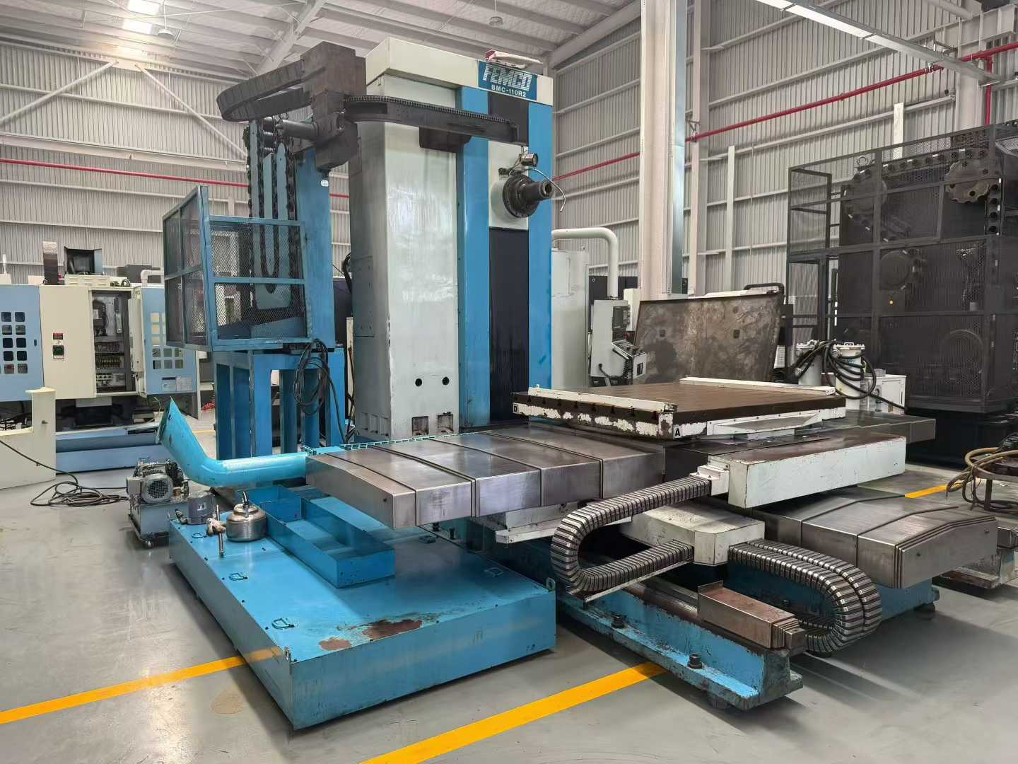
Boring Machine Setup Guide: Key Steps for Accurate On-Site MachiningA reliable boring machine setup begins before the first cut. On-site machining accuracy depends on the condition of the damaged bore, the rigidity of the installation, correct boring bar alignment and measurements taken at each critical stage. Always follow the equipment manufacturer’s manual, approved safety procedures and the specific requirements of the repair project. 1. Inspect the Work Area and Damaged Bore Confirm that the machine, support points, workpiece and surrounding area are suitable for on-site machining. Remove loose debris, oil contamination and obstructions that could affect mounting or measurement. Inspect the existing bore for cracks, distortion, weld buildup, broken fasteners or damage that may change the machining plan. Check access for the boring bar, drive unit, power supply and measuring tools. Identify lifting, guarding and lockout requirements before installation. If the workpiece is unstable or access is restricted, correct those conditions before continuing rather than compensating through cutting adjustments. 2. Measure Before Alignment Record the existing bore condition and the relationship between the bore, surrounding faces and available support locations. Use suitable calibrated measuring equipment and take readings at more than one position where access permits. These measurements establish the starting condition and help determine whether the proposed boring bar travel and final machining allowance are adequate. Do not assume that a visually clean bore is straight or concentric. Taper, ovality, offset and wear can affect alignment decisions. Document the readings so the final result can be compared with the project requirement. 3. Align and Secure the Boring System Boring bar alignment should be established from the required finished bore location, not simply from the edge of the existing hole. Position the support bearings or mounting brackets according to the machine manual and the workpiece geometry. Check the bar position at multiple reference points, then adjust until the axis matches the required machining centerline. After alignment, tighten all mounting hardware in the specified sequence and verify that the supports remain stable. Secure the workpiece and machine against movement, vibration and accidental contact. Recheck alignment after tightening because clamping force or uneven support can shift the boring bar. 4. Set Cutting Parameters and Bore Set tool projection, feed, rotational speed and depth of cut according to the machine manual, tool condition, material, bore size and required finish. Use conservative starting conditions when the material condition or rigidity is uncertain. Confirm tool clearance, rotation direction, chip evacuation and guarding before starting the drive. During the cut, monitor vibration, unusual noise, tool wear and mounting movement. Stop the operation if the setup changes or if cutting conditions become unstable. A controlled setup is more important than forcing a higher removal rate. 5. Verify the Finished Bore After machining, clean the bore and measure the finished diameter at the locations required by the project specification. Check for taper, ovality, surface damage and the required relationship to adjacent features. Record the final results and compare them with the acceptance criteria before removing the equipment. Frequently Asked Questions How long does an on-site boring machine setup take? There is no universal installation time. The duration depends on access, bore size, mounting complexity, alignment requirements, site conditions and the inspection process. Confirm the expected schedule from the equipment manual and project plan rather than using a fixed estimate. How is the boring bar aligned? Measure the required bore axis, position the supports and adjust the bar at multiple reference points. Recheck alignment after all supports and clamps are tightened. Which setup errors affect accuracy most? Unstable supports, incorrect centerline measurement, bar deflection, workpiece movement and failure to recheck alignment can directly affect bore size, straightness and concentricity. What must be checked before machining starts? Verify mounting security, bar clearance, tool condition, power and controls, guarding, workpiece stability, measurement records and the approved cutting parameters.
-
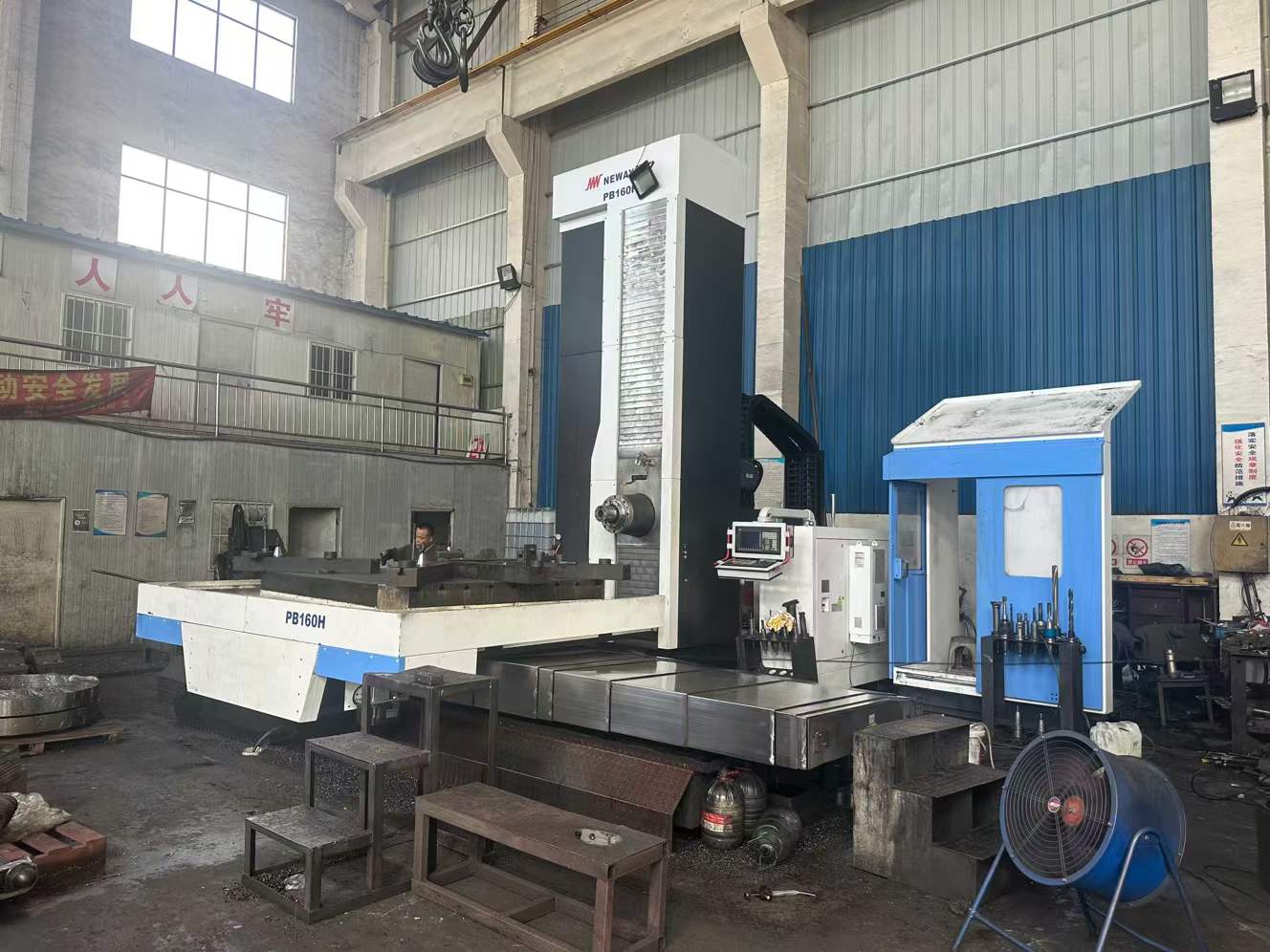
Boring Machine Accuracy: Key Factors That Affect Machining ResultsA bore can meet its diameter requirement yet still fail assembly because its axis is misplaced, its shape is distorted or adjacent bores are misaligned. Boring machine accuracy therefore needs to be assessed against the drawing’s dimensional, geometric and surface finish requirements. For portable line boring repairs on excavator pivots, loader frames and similar assemblies, the machine, mounting arrangement and workpiece form one machining system. Published machine capability alone cannot establish the finished result. Accuracy Factors Checklist Factor Effect on results Control before finishing Machine and bar rigidity Deflection and vibration can produce taper, chatter or size variation. Minimize unsupported bar length and tool overhang; check supports and bearing condition. Alignment and mounting An incorrect bar axis produces bores in the wrong position. Reference approved datums and recheck alignment after securing mounts. Tool condition and cutting parameters Wear, built-up edge and excessive cutting forces alter size and finish. Check insert condition, tool clamping, speed, feed and depth of cut. Workpiece condition Clamping distortion, weld stress and heat can change geometry. Inspect cracks, weld repairs, support points and temperature. Measurement method Limited sampling or unsuitable gauges can miss defects. Use calibrated instruments with resolution and uncertainty appropriate to the tolerance. Control the Setup Before Adjusting the Cut Establish the required bore axis from the drawing or an approved repair reference. Worn bores may no longer represent the original centerline. For line boring accuracy, verify the relationship between all relevant bores, rather than centering independently on each damaged opening. Secure the component and supports, then check that the bar rotates freely and the alignment remains stable. Stop the drive before adjusting tools or supports. A light trial cut can reveal chatter or uneven engagement, but it does not prove positional accuracy. Select cutting parameters for the material, insert and setup rigidity. Excessive cutting force can deflect the bar; an excessively light cut can cause rubbing. Leave controlled finishing stock, monitor tool wear and investigate dimensional drift before continuing. Verify Size, Form and Axis Separately Clean and deburr the bore before inspection. Measure diameter at multiple depths and angular positions to screen for taper and ovality. These readings alone do not establish roundness, cylindricity or coaxiality; use an inspection method suited to each drawing requirement. Account for workpiece and instrument temperature. Where clamping may distort the component, agree whether acceptance measurements apply in the clamped or released condition. Record the setup, measurement locations and results. Accuracy and Alignment FAQ Does correct alignment guarantee an accurate bore? No. Alignment establishes the intended axis, while rigidity, tooling, cutting conditions and workpiece stability determine whether machining maintains it. What information is needed to assess achievable accuracy? Provide bore dimensions, spacing, material, required tolerances, datum references, repair history, access restrictions and the proposed inspection method. Any accuracy commitment should be confirmed for those conditions.
-
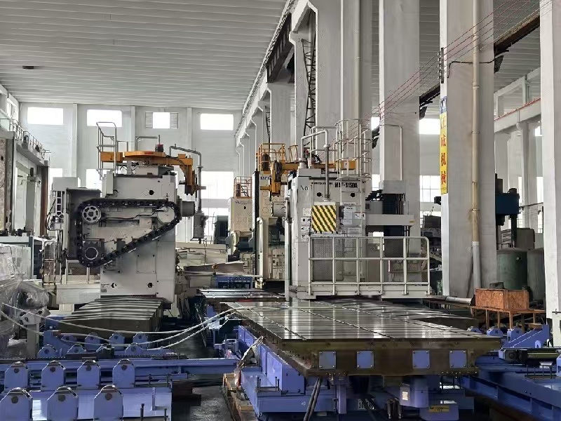
Boring Machine Bore Diameter: How to Choose the Right Machining RangeChoosing the correct boring machine bore diameter starts with the workpiece, not the machine catalogue. The finished bore, existing hole condition, access length and material determine whether a machine can complete the job efficiently. A quoted maximum diameter alone does not show whether the machine can enter the smallest hole or maintain a practical setup across the full machining range. Start with the workpiece and the finished bore Record the smallest and largest bore diameters that the machine must produce. Also note whether the hole is a through bore, blind bore, stepped bore or aligned set of holes. Measure the available access around the workpiece and the distance from the mounting position to the bore centerline. The minimum bore diameter must allow the boring bar, cutting tool and any required support components to enter the hole with safe clearance. The maximum bore diameter must include the actual cutting diameter required after considering the existing hole, machining allowance and finishing pass. If a job involves several bore sizes, use the complete range rather than selecting the machine from the largest size only. Use the real boring machine working range Workpiece condition Range to verify Why it matters Small existing hole Minimum tool and bar entry diameter Determines whether the tool can reach the bore without interference. Large repair bore Maximum finished cutting diameter Confirms that the machine can remove the required material and finish the bore. Deep or offset bore Boring bar length and support position Controls reach, clearance and the usable portion of the diameter range. Stepped or multiple bores Complete diameter sequence Shows whether one configuration can cover the job without repeated changes. The usable boring machine working range is narrower than a headline range when the workpiece requires a long reach, large material removal or restricted access. Confirm the machine's operating diameter at the required boring bar length, because a configuration suitable for a short bore may not provide the same practical capability at greater depth. Match boring bar length, tooling and material Boring bar length should be based on the distance from the mounting point to the deepest cutting location. Select the shortest bar that reaches the required position while preserving clearance. Excessive length can reduce rigidity and limit practical cutting conditions, especially in hard steel or interrupted repair surfaces. Tool selection also affects the usable bore range. Small diameters may require compact cutters and suitable insert clearance; larger diameters may require a different bar, cutter arrangement or support method. Cast iron, carbon steel, alloy steel and other materials can require different cutting tools and machining approaches. These choices should be confirmed together with the diameter and reach rather than treated as separate specifications. Submit actual dimensions for configuration confirmation Before ordering, provide the supplier with the smallest and largest finished bore, existing bore sizes, bore depth, workpiece material, machining allowance, access restrictions and required bore locations. A drawing or clear dimensional sketch allows the supplier to confirm the machine range, boring bar length and tooling configuration for the actual repair or production task. FAQ Is the maximum bore diameter enough for machine selection? No. The minimum bore, required reach, cutting allowance and tool clearance are equally important. A machine may reach the largest diameter while being unsuitable for the smallest hole or deepest section. How does boring bar length affect the machining range? A longer bar extends reach but can change the practical working range because access, rigidity and tool clearance become more restrictive. Confirm the diameter range at the required reach. What information should be sent for a bore range check? Send the real workpiece drawing or dimensions, finished bore range, existing hole sizes, bore depth, material, allowance and access conditions. These details support configuration confirmation before purchase.
-
How to Choose a Boring Machine for Excavator and Loader RepairsChoosing a boring machine for excavator repair starts with the damaged part. Pin bores, bucket linkages and boom connections place different demands on alignment, access and machine setup. For loader work, the same principle applies to articulation points and pivot bores. Identify the repair location first, then match the machine to the bore diameter, available working space and required installation method. Match the machine to the damaged component Equipment Part Typical Repair Requirement Excavator pin bores Restore worn or oval bores while keeping the bore aligned through the connected lug structure. Bucket linkage Repair multiple linkage bores with controlled positioning around compact, obstructed assemblies. Boom and arm connections Handle larger pivot bores and maintain alignment between separated mounting ears. Loader articulation points Recondition central hinge and pin bores where access, clearance and machine positioning affect setup. Loader pivot bores Remove wear and prepare the bore for a replacement or repaired pin with consistent geometry. Start with the bore problem Excavator pin bores commonly develop ovality, uneven wear and clearance around the pin. A suitable boring machine for excavator repair should allow the operator to establish a stable reference, align the cutting bar with the original bore centerline and remove only the material needed for the repair. If several connected bores are involved, the machine must support a setup that preserves their relationship. For bucket linkage and boom or arm connections, access can determine machine fit. Check whether the boring bar can pass through the assembly, whether the mounting points provide enough room for supports, and whether nearby hydraulic lines or structural members restrict positioning. A compact setup may be essential for on-site repair, while a larger and more rigid arrangement may suit a major pivot bore. Requirements for a boring machine for loader repair Loader articulation points and pivot bores require careful attention to alignment because the repaired bore affects hinge movement and pin loading. Before selecting equipment, record the bore diameter, bore length, distance between bores, access direction and available clearance around the loader frame. These details help determine the cutting-bar arrangement, support placement and whether the repair can be completed without removing the full assembly. Site conditions also influence the choice. Confirm the power supply, lifting and handling options, working height, weather exposure and space for measurement and machining. Buyers should verify the machine’s usable diameter range, boring-bar length, mounting method, alignment procedure and suitability for the specific excavator or loader component. Information to send before requesting a recommendation Equipment type and the exact repair location Measured bore diameter, length and wear condition Pin dimensions and whether bushes will be installed Photos showing access, obstructions and surrounding structure On-site or workshop repair conditions, including available power This information allows a supplier to assess machine fit against the actual repair rather than the equipment model alone. FAQ: excavator and loader bore repairs Can one machine repair excavator pin bores and loader articulation points? It may, if its diameter range, bar length, support arrangement and mounting options suit both components. Verify each repair dimension and access condition before selecting a general-purpose setup. What should be measured on a worn excavator bore? Measure the existing bore diameter at several positions, identify ovality and taper, record bore length, and check the mating pin and surrounding lug alignment. These measurements define the machining allowance and setup requirements. What information is needed for a boring machine for loader repair? Provide the loader model, articulation or pivot location, bore and pin dimensions, photos of the working area, access direction, clearance and site power conditions.
-
Boring Machine for Mining Equipment: What Buyers Should ConsiderMining equipment repair rarely takes place in a clean workshop. A boring machine for mining equipment must work around abrasive dust, moisture, limited access, heavy components and urgent production schedules. For procurement teams, the right choice depends on the actual repair environment and the equipment being serviced, not only on the machine's advertised capacity. Start with the Mining Repair Environment First assess where mining equipment boring repair will occur. An underground site may require a compact, portable machine that can be positioned around a loader, excavator or haul truck without removing the complete structure. An open-pit maintenance area may allow more room, but still exposes equipment to dust, vibration, mud and temperature changes. Ask suppliers how the machine is protected during transport and operation. Check the accessibility of controls, the method used to secure the machine to the workpiece, and how easily chips and contamination can be cleared from critical moving parts. A field repair system should also support practical setup, alignment and inspection procedures when workshop equipment is unavailable. Match the Machine to Equipment Constraints Mining repair requirement What to verify Why it matters Large pins and pivot bores Applicable bore diameter range, bar length and tooling options Prevents the machine from being undersized for major joints Restricted access Portable configuration, mounting method and clearance requirements Determines whether repair can be completed in position Hard or damaged material Drive power, feed control and compatible cutting tools Supports stable cutting under demanding repair conditions Multiple equipment types Adjustability, modular components and available accessories Improves utilization across different machines and bore sizes Do not evaluate bore diameter alone. Confirm the complete working envelope: minimum and maximum bore size, usable boring-bar length, mounting span, alignment method and access around the damaged joint. The machine must also suit the metallurgy and damage condition commonly found in the fleet. Evaluate Power, Durability and Maintenance Power should be considered together with control. A suitable drive system needs enough torque for the planned cutting tools and materials while maintaining controlled rotation and feed. Ask for application guidance based on the actual equipment, bore dimensions and repair material rather than relying on a general power figure. For mine-site use, inspect wear-prone parts, seals, bearings, cables, gear components and mounting hardware. Request a clear maintenance schedule and identify which parts can be inspected or replaced by site technicians. Spare-part availability is a procurement issue, not an after-sales detail: delays involving a drive component, cutter or fastening element can extend equipment downtime. Check Engineering Support Before Purchase Supplier support should cover configuration, setup, alignment, tooling selection and troubleshooting. Before issuing a purchase order, request a documented list of included components, optional accessories, recommended consumables and spare parts. Verify training or commissioning arrangements where the repair team has limited experience with portable line boring. Also confirm how the supplier handles unusual bore sizes, difficult access and repairs requiring additional fixturing. A durable machine is valuable only when the site team can install, operate, maintain and restore it with dependable technical support. FAQ: Mining-Site Durability and Maintenance Can a portable boring machine be used in underground mining repairs? It can be suitable when its dimensions, mounting method, power source and access requirements match the underground work area. Confirm transport limitations and the available space around the damaged bore before selection. What maintenance information should buyers request? Request inspection intervals, lubrication requirements, wear-part identification, troubleshooting procedures and a recommended spare-parts list. The documentation should explain which maintenance tasks can be completed at the mine site. Why is engineering support important for mining equipment boring repair? Mining repairs often involve irregular access, large structures and varying bore conditions. Technical support helps determine the correct machine configuration, tooling and alignment method before equipment downtime becomes longer.
-
How Boring Machines Restore Worn Bores in Heavy MachineryWhen a pin, bushing or shaft moves excessively in a heavy-machine bore, replacing the loose component alone may not solve the problem. The bore may be oval, tapered, scored or out of position. A boring machine for heavy machinery can restore the bore’s geometry by machining it to a planned size and alignment, often with the work performed on the machine rather than removing the full structure. Diagnose the damage before machining Start by cleaning the joint and recording the machine model, component location, bore dimensions and symptoms. Measure the bore at multiple positions and orientations to identify wear, ovality and taper. Inspect for cracks, fretting, corrosion, damaged welds and movement around the bore. Check the pin or shaft and mating bores as well: a worn pin, failed lubrication or misaligned joints can cause repeat damage. Common cause Typical clue Repair consideration Insufficient lubrication or contamination Scoring, heat marks or abrasive wear Correct the lubrication or sealing issue as part of the repair plan. Loose fit or worn pin Knocking, fretting or uneven contact Assess both bore and pin; machining only the bore may leave excessive clearance. Misalignment or structural movement Uneven wear across connected bores Establish the required common axis before line boring. Corrosion, impact or fatigue Pitting, deformation or visible cracking Determine whether the material can be safely repaired before cutting. Alignment determines the repair For connected joints, line boring worn bores aims to restore their relationship to a common axis. A bore can be round yet still be incorrectly positioned relative to the next bore. The repair plan therefore needs reference points, the required axis, finished diameter and fit requirements, plus any limits on material removal. If damage is severe, cracks are present or the original geometry cannot be established, confirm the repair method with the equipment owner or a qualified engineering authority before machining. Machine, then verify the finished joint After fixing the setup and boring bar, the technician aligns the tooling to the agreed reference, removes material in controlled passes and checks progress against the target. Depending on the repair design, the finished bore may receive a sleeve or bushing; the installation and final size must match the specified fit. Protect nearby surfaces and components from chips, and follow site isolation and machine-support procedures throughout the work. Final inspection should verify diameter at several points, roundness, alignment across the connected bores and surface condition. Check the installed pin or bushing fit against the applicable drawing or repair specification. Record measurements and any deviations, then address the cause of wear before returning the machine to service. Information to provide when assessing a repair Share bore locations and access constraints, measured dimensions, photos of damage, machine and component details, pin or bushing condition, and the required fit or drawing. Include operating symptoms and known lubrication, impact or alignment issues. These job details help determine whether on-site boring, a sleeve-based repair or further engineering assessment is appropriate. FAQ Can a worn bore be repaired without removing the component? Often, portable line boring can be set up on installed machinery, but access, setup stability, damage severity and alignment references determine feasibility. How do you confirm the repair is complete? Measure the finished diameter and geometry, verify the axis where bores are connected, and check the pin or bushing fit against the repair specification. Will boring alone prevent the bore from wearing again? No. Boring restores geometry; recurring wear may continue unless the underlying cause, such as poor lubrication, contamination, a damaged pin or misalignment, is corrected.
-
Boring Machine Applications in Construction Equipment RepairWhen a pin joint develops play, replacing the pin alone may not solve the problem. Wear can leave the housing bore oval, tapered or out of alignment. A boring machine for construction equipment repair restores the bore so the joint can be fitted with a correctly sized pin or bush. This work is often performed on the machine in the field when removing a large component would add substantial downtime. Where bore wear occurs on construction equipment Repeated articulation, impact loading, inadequate lubrication and contamination can wear the bores that support pins and bushes. The repair target is the damaged joint bore, not simply the visible pin. Before machining, the technician needs to identify the joint layout, access, material condition and the relationship between connected bores. Equipment Typical bore Repair purpose Excavator Boom, arm and bucket pin bores Restore pin fit and joint alignment Loader Lift-arm and bucket pivot bores Correct wear at heavily cycled pivots Backhoe Dipstick, boom and stabilizer pin bores Re-establish fit across linkage joints Crane Boom and linkage pivot bores Address wear at structural articulation points Hydraulic equipment Cylinder-end and mounting pin bores Restore the connection between cylinder and structure How boring repair addresses the damage Construction equipment boring repair typically starts with inspection and measurement. The repair team checks bore diameter, roundness, wear pattern and alignment with related bores. If the housing is suitable for repair, a portable line boring setup machines the damaged bore to a controlled, consistent diameter. Depending on the repair plan, the bore may then receive a bush, or be finished to suit the specified pin or bearing arrangement. Where two or more bores form one pivot line, their alignment matters as much as the individual diameters. Machining them in a common setup can help restore the intended axis. The required dimensions and fit should come from the equipment specification or an agreed repair drawing; they should not be assumed from the pin size alone. Field conditions shape the repair plan Access, nearby structures, available setup space and the condition of the surrounding material affect whether on-site boring is practical. Cracks, severe distortion, damaged welds or a bore near a highly loaded structural area may require additional inspection or a different repair sequence. The machine must also be isolated and securely supported before work begins, following site and equipment safety procedures. For a field assessment, document the machine and joint location, report the symptoms, and provide measurements or photographs where available. Confirm whether connected bores need to be machined on the same axis, whether a bush will be installed, and what final fit is required. These details help establish a realistic repair scope before equipment is mobilized. Frequently asked questions Which excavator parts commonly need bore repair? Boom, arm and bucket pin joints are common locations, as are other pivot connections showing looseness or uneven wear. Inspection determines whether the bore, pin, bush or several parts need attention. Can loader pivot bores be repaired on site? Often, but feasibility depends on access, setup conditions, damage severity and the required machining sequence. A site assessment can establish whether portable boring is appropriate. Does every worn bore need a new bush? No. The repair method depends on the equipment design, bore condition and specified fit. Confirm the intended finished dimensions and component arrangement before machining.
-
How to Select a Boring Machine for Heavy Equipment Repair and MaintenanceWhen an excavator, loader or crane develops play at a pin joint, the repair decision starts with the damaged bore and where the work must be done. Selecting a boring machine for heavy equipment means matching the machine’s working range and setup to the equipment, bore geometry and repair environment, not choosing by machine size alone. Start with the equipment and bore Repeated loading, vibration and movement can wear pivot bores out of round or enlarge them. Damage may affect a boom, arm, bucket, blade, steering joint, stabilizer or other connected structure. Bulldozers and mining machinery can present similar issues, often with limited access and substantial components that are difficult to transport. Before comparing machines, identify the bore location, nominal and measured diameter, bore length, spacing between bores, and whether the holes must share a common axis. Also note obstructions, available mounting points and the clearance needed for the bar, supports and drive. These details define the required working range and setup options for heavy equipment line boring. Match the machine to the repair setting Repair scenario Selection priority Excavator boom, arm or bucket joint Bar reach, mounting access and alignment across separated bores Loader linkage or articulation joint Setup flexibility around the frame and room for the drive and supports Bulldozer blade or ripper attachment Access around large structures and practical positioning at the machine Crane pivot or stabilizer connection Clearance, stable mounting and the required bore length Mining machinery with limited shutdown access Transportability, on-site setup requirements and available power For on-site boring repair, consider whether the machine and accessories can be moved to the equipment, whether the work area allows safe setup, and what power and lifting support are available. If the component can be removed and handled in a workshop, compare that option with field machining based on transport, downtime and access constraints. Check configuration before purchase Compare the machine’s stated bore-diameter range, bar length, support arrangement, drive configuration and mounting method with the actual jobs you expect to handle. Confirm whether the configuration can accommodate the bore spacing and access limits, and whether the required accessories are included or optional. A nominal diameter range alone does not confirm that a machine can reach a particular joint or maintain the required alignment. Share equipment type, bore dimensions, distance between bores, photos of the joint and site constraints when requesting a configuration. Ask the supplier to verify working range, mounting approach, power requirements and any accessories needed for the stated job. Keep this selection decision separate from the repair procedure: machining sequence and bore restoration methods depend on the damage and repair specification. Questions buyers often ask Can one boring machine cover excavators, loaders and cranes? Possibly, if its working range, bar length, mounting options and accessories suit the different joints. Verify each target bore and setup rather than assuming one configuration fits every machine. What information is needed for an on-site recommendation? Provide bore diameter and length, spacing between bores, joint photos, access restrictions, available power and whether the equipment can be moved or dismantled. Does a larger machine always suit heavier equipment? No. The useful choice is the configuration that reaches and mounts securely at the bore while meeting the job’s dimensional and alignment requirements. Oversizing alone does not solve access or setup problems.
-
Portable vs Stationary Boring Machine: Key Differences for Industrial UseChoosing between a portable boring machine and a stationary boring machine depends on where the work must be performed, how the workpiece is supported, and how much setup the job can accept. Portable equipment is designed to bring line boring capability to large or immobile components. Stationary equipment is better suited to a controlled workshop environment with repeatable loading, alignment and production procedures. The right choice is therefore determined by the repair or machining situation, rather than by a universal winner. Two Different Industrial Use Cases A portable boring machine is generally selected when transporting the component is impractical. Typical situations include excavator booms, loader arms, crane structures, construction equipment frames and large machinery that must remain at a plant or worksite. The machine is positioned and secured around the damaged bore, allowing machining to take place in position. A stationary boring machine is installed in a workshop or production area. The component is brought to the machine, supported on the bed or fixture, and processed under controlled operating conditions. This arrangement is useful for repeat repairs, batch work, larger machining programs and components that can be safely moved. Portable vs Stationary Boring Machine: Direct Comparison Factor Portable boring machine Stationary boring machine Mobility Moves to the component; suitable for field or in-situ repair Remains in a fixed workshop location Installation Requires local setup, mounting, alignment and site preparation Uses established foundations, fixtures and workshop services Workpiece size Practical for oversized or non-transportable structures Limited by machine capacity, bed dimensions and handling equipment Operating environment May be exposed to restricted access, contamination or weather Offers a more controlled machining environment Best-fit work On-site repair, emergency restoration and large equipment Repeatable workshop repair, production and planned machining Trade-Offs That Affect the Decision Portability reduces transportation and disassembly requirements, but it shifts more responsibility to the jobsite. The team must verify access, mounting surfaces, structural stability, power availability, chip control and measurement access before machining begins. Setup quality directly affects alignment and final bore condition. Stationary equipment usually simplifies fixturing and process control. However, transporting a heavy component may require lifting equipment, permits, disassembly and additional downtime. The machine may also be unsuitable if the component exceeds its working envelope or cannot be positioned securely. For a repair involving one large machine that cannot leave service easily, the cost of mobilization and setup for portable equipment may be justified. For repeated components or planned workshop work, fixed fixturing and established procedures may improve consistency and throughput. Questions to Confirm Before Selecting Can the component be removed and transported without excessive downtime or handling risk? What are the required bore diameter, center distance, access limitations and alignment references? Does the worksite provide stable mounting points, power, lighting, lifting support and adequate chip management? Is the job a one-time field repair, or will similar components be machined repeatedly? FAQ Is a portable boring machine suitable for workshop work?Yes. It can be used in a workshop when the component is too large for a fixed machine or when in-position machining avoids disassembly. The workshop must still provide suitable support, alignment access and safe operating space. Which option is better for oversized equipment?A portable boring machine is usually the practical option when the equipment cannot be transported or exceeds the stationary machine's working envelope. The mounting and alignment plan should be confirmed before mobilization. Does stationary equipment always provide better results?Not automatically. A stationary machine benefits from controlled fixturing and workshop conditions, while a properly installed portable machine can solve alignment and repair problems directly on the equipment. The result depends on machine suitability, setup and process control.