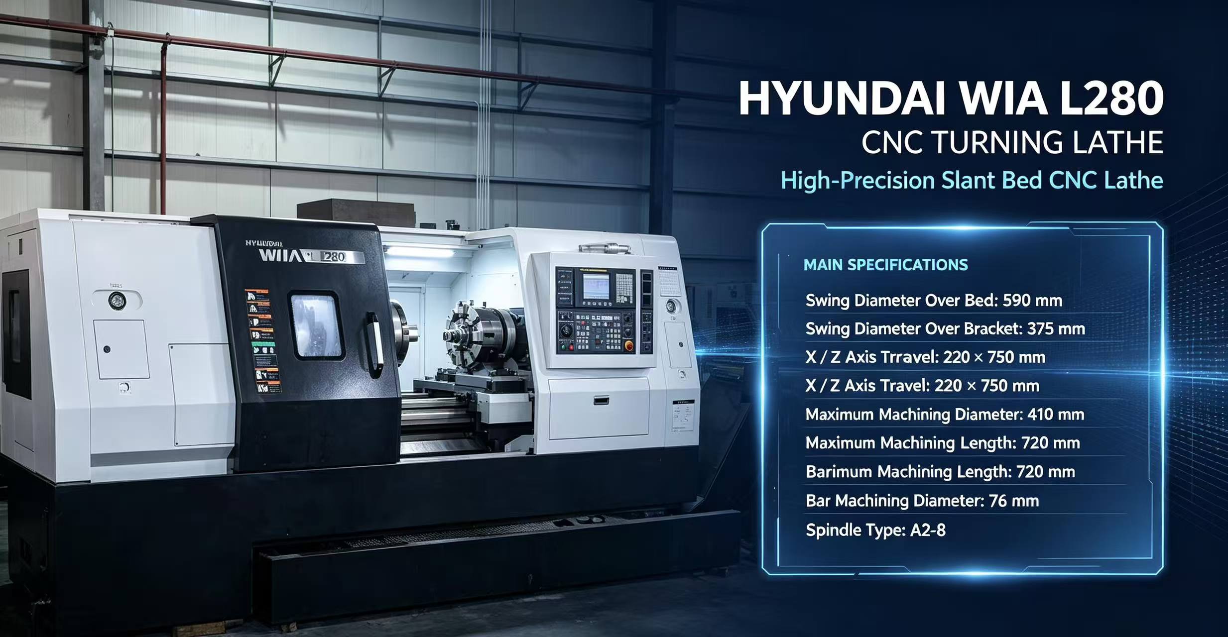
How do I check the electrical box to help you choose a used YCM?
Step 1: Safety Preparation and Static Visual Inspection (Power Off Operation)
Complete Power Off: Ensure the main power switch for the used YCM is turned off and a warning sign is displayed. Ideally, completely disconnect the upstream power supply. This is a prerequisite for all operations.
Appearance and Cleaning: Open the electrical box door and first observe the overall cleanliness of the interior. Thick layers of dust and oil indicate that the equipment is operating in a harsh environment or lacks maintenance, which will severely affect heat dissipation and cause premature aging of components. Look for metal shavings, which may indicate insufficient protection during processing.
Structural Integrity: Check the inside of the box for rust, especially near the cooling system. Moisture corrosion is a major enemy of circuit boards. Check the cable trays and harnesses for neatness and for any messy, haphazardly installed or modified wires. Standardized wiring indicates the maintenance level of the original manufacturer or previous owner.
Step 2: Critical Component Status Inspection (Power Off Operation)
Contactors and Relays: Locate the main power contactor, spindle contactor, servo drive contactor, etc. Check their contacts for severe electrical corrosion (burning, unevenness). Minor signs of use are normal, but severe electrolytic corrosion indicates excessive current load or frequent start-stop cycles, posing a potential hazard.
PLC and I/O Modules: Observe the status indicator lights of the programmable logic controller (PLC) unit. Record its model number for future spare parts retrieval. Check the I/O module wiring for secure connections.
Servo Drivers and Spindle Drivers: This is the core of the electrical box. Carefully observe the driver unit for any residual alarm codes (some may retain historical alarms even after power failure). Check its display panel for any abnormalities. Look for signs of capacitor bulging or leakage, which are clear signs of component aging.
Terminals and Cables: Gently wiggle the main power connectors and motor power cable terminals by hand (wearing gloves is acceptable) to check for looseness. Loose terminals can overheat due to excessive contact resistance, posing a significant danger. Check cable connectors for signs of overheating, melting, or deformation.
Step 3: Power-On Dynamic Check (Power on, but do not start the spindle and servo)
Sequential Power-On: Close the main power supply, but do not immediately start the machine tool in the "Ready" state.
Observation and Listening: Listen for any abnormal "buzzing" discharge sounds or "clicking" sounds from relays malfunctioning inside the electrical box. Also, note any sudden burning odor.
Check Power Supply Voltage: Use a multimeter to check if the three-phase input voltage is balanced and stable at the test points or input terminals of the power module. This is fundamental for the normal operation of all electrical components.
Driver Self-Test: Observe the indicator lights of the servo and spindle drives. Under normal circumstances, after power-on, a self-test should be performed, followed by a "ready" indicator or a similar green light, not an alarm red light. If an alarm sounds immediately upon power-on, it indicates a hardware or parameter fault, requiring close monitoring.
Fan and Cooling: Confirm that the cooling fan in the electrical box is operating normally. Poor heat dissipation is one of the main causes of electronic component failure.
Step Four: Machine Tool Function Testing
This is crucial for linking electrical status with mechanical performance.
In manual mode, slowly move each axis, paying attention to any abnormal sounds or alarms from the servo drive.
Start the spindle at low speed and observe the spindle drive's operating status. Run the tool magazine and check whether the related relays and sensors operate accurately and decisively.
More Articles
-
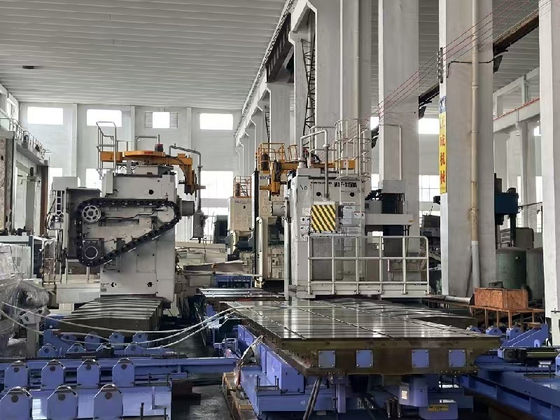
Boring Machine Bore Diameter: How to Choose the Right Machining RangeChoosing the correct boring machine bore diameter starts with the workpiece, not the machine catalogue. The finished bore, existing hole condition, access length and material determine whether a machine can complete the job efficiently. A quoted maximum diameter alone does not show whether the machine can enter the smallest hole or maintain a practical setup across the full machining range. Start with the workpiece and the finished bore Record the smallest and largest bore diameters that the machine must produce. Also note whether the hole is a through bore, blind bore, stepped bore or aligned set of holes. Measure the available access around the workpiece and the distance from the mounting position to the bore centerline. The minimum bore diameter must allow the boring bar, cutting tool and any required support components to enter the hole with safe clearance. The maximum bore diameter must include the actual cutting diameter required after considering the existing hole, machining allowance and finishing pass. If a job involves several bore sizes, use the complete range rather than selecting the machine from the largest size only. Use the real boring machine working range Workpiece condition Range to verify Why it matters Small existing hole Minimum tool and bar entry diameter Determines whether the tool can reach the bore without interference. Large repair bore Maximum finished cutting diameter Confirms that the machine can remove the required material and finish the bore. Deep or offset bore Boring bar length and support position Controls reach, clearance and the usable portion of the diameter range. Stepped or multiple bores Complete diameter sequence Shows whether one configuration can cover the job without repeated changes. The usable boring machine working range is narrower than a headline range when the workpiece requires a long reach, large material removal or restricted access. Confirm the machine's operating diameter at the required boring bar length, because a configuration suitable for a short bore may not provide the same practical capability at greater depth. Match boring bar length, tooling and material Boring bar length should be based on the distance from the mounting point to the deepest cutting location. Select the shortest bar that reaches the required position while preserving clearance. Excessive length can reduce rigidity and limit practical cutting conditions, especially in hard steel or interrupted repair surfaces. Tool selection also affects the usable bore range. Small diameters may require compact cutters and suitable insert clearance; larger diameters may require a different bar, cutter arrangement or support method. Cast iron, carbon steel, alloy steel and other materials can require different cutting tools and machining approaches. These choices should be confirmed together with the diameter and reach rather than treated as separate specifications. Submit actual dimensions for configuration confirmation Before ordering, provide the supplier with the smallest and largest finished bore, existing bore sizes, bore depth, workpiece material, machining allowance, access restrictions and required bore locations. A drawing or clear dimensional sketch allows the supplier to confirm the machine range, boring bar length and tooling configuration for the actual repair or production task. FAQ Is the maximum bore diameter enough for machine selection? No. The minimum bore, required reach, cutting allowance and tool clearance are equally important. A machine may reach the largest diameter while being unsuitable for the smallest hole or deepest section. How does boring bar length affect the machining range? A longer bar extends reach but can change the practical working range because access, rigidity and tool clearance become more restrictive. Confirm the diameter range at the required reach. What information should be sent for a bore range check? Send the real workpiece drawing or dimensions, finished bore range, existing hole sizes, bore depth, material, allowance and access conditions. These details support configuration confirmation before purchase.
-
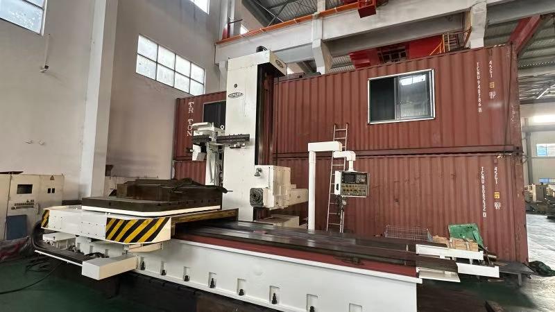
Boring Machine Applications in Construction Equipment RepairWhen a pin joint develops play, replacing the pin alone may not solve the problem. Wear can leave the housing bore oval, tapered or out of alignment. A boring machine for construction equipment repair restores the bore so the joint can be fitted with a correctly sized pin or bush. This work is often performed on the machine in the field when removing a large component would add substantial downtime. Where bore wear occurs on construction equipment Repeated articulation, impact loading, inadequate lubrication and contamination can wear the bores that support pins and bushes. The repair target is the damaged joint bore, not simply the visible pin. Before machining, the technician needs to identify the joint layout, access, material condition and the relationship between connected bores. Equipment Typical bore Repair purpose Excavator Boom, arm and bucket pin bores Restore pin fit and joint alignment Loader Lift-arm and bucket pivot bores Correct wear at heavily cycled pivots Backhoe Dipstick, boom and stabilizer pin bores Re-establish fit across linkage joints Crane Boom and linkage pivot bores Address wear at structural articulation points Hydraulic equipment Cylinder-end and mounting pin bores Restore the connection between cylinder and structure How boring repair addresses the damage Construction equipment boring repair typically starts with inspection and measurement. The repair team checks bore diameter, roundness, wear pattern and alignment with related bores. If the housing is suitable for repair, a portable line boring setup machines the damaged bore to a controlled, consistent diameter. Depending on the repair plan, the bore may then receive a bush, or be finished to suit the specified pin or bearing arrangement. Where two or more bores form one pivot line, their alignment matters as much as the individual diameters. Machining them in a common setup can help restore the intended axis. The required dimensions and fit should come from the equipment specification or an agreed repair drawing; they should not be assumed from the pin size alone. Field conditions shape the repair plan Access, nearby structures, available setup space and the condition of the surrounding material affect whether on-site boring is practical. Cracks, severe distortion, damaged welds or a bore near a highly loaded structural area may require additional inspection or a different repair sequence. The machine must also be isolated and securely supported before work begins, following site and equipment safety procedures. For a field assessment, document the machine and joint location, report the symptoms, and provide measurements or photographs where available. Confirm whether connected bores need to be machined on the same axis, whether a bush will be installed, and what final fit is required. These details help establish a realistic repair scope before equipment is mobilized. Frequently asked questions Which excavator parts commonly need bore repair? Boom, arm and bucket pin joints are common locations, as are other pivot connections showing looseness or uneven wear. Inspection determines whether the bore, pin, bush or several parts need attention. Can loader pivot bores be repaired on site? Often, but feasibility depends on access, setup conditions, damage severity and the required machining sequence. A site assessment can establish whether portable boring is appropriate. Does every worn bore need a new bush? No. The repair method depends on the equipment design, bore condition and specified fit. Confirm the intended finished dimensions and component arrangement before machining.
-
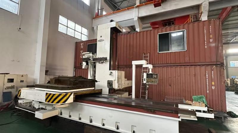
Boring Machine Cost Guide: What Affects the Price of Industrial Equipment?Two boring machines intended for similar repair work canreceive very different quotations because the price reflects more than the machine’s basic size. Machine type, working range, drive power, accuracy requirements, tooling and included automation all affect the final configuration. To compare a boring machine price accurately, compare the scope of supply and the job requirements, not just the headline figure. What drives the quotation? Price factor Why it affects cost Details to specify Machine type and setup Portable systems and larger stationary equipment have different structures and intended applications. Equipment type, work location and setup constraints Bore size and machining range Required diameter, bar length and travel determine the working envelope and compatible components. Minimum and maximum bore diameter, machining length and access Power and duty Drive requirements depend on the material, cutting conditions and expected workload. Workpiece material, typical jobs and operating frequency Accuracy and tooling Accuracy requirements and the tooling package influence component selection and what must be supplied. Required results, cutters, mounts and other tooling needs Automation and customization Controls, optional functions and non-standard configurations add scope to the build. Required automation, special interfaces and quantity Configuration matters more than a bare price A lower-priced machine may have a narrower machining range, fewer included tools or less automation. A higher quotation may include a broader configuration or options that are unnecessary for a particular job. Neither price alone establishes suitability. For a portable boring machine price comparison, check that the quoted setup can reach the bore, fit the available work area and perform the required operation. Accuracy should also be described in terms of the work to be done. Share the required result and relevant workpiece details so the supplier can quote a configuration against the application. Avoid comparing quotations that assume different tooling, accessories, automation or customization. Prepare information for a useful quote For a meaningful boring machine cost estimate, provide the bore diameter range, machining length, material, workpiece or equipment details, site access constraints and expected operating frequency. List required tooling, accuracy expectations, automation and any special mounting or interface requirements. Include the purchase quantity and identify which accessories should be included. Ask suppliers to show the proposed configuration and included items in the quotation. This makes differences easier to trace and helps prevent a low initial figure from omitting components needed for the intended work. Submit the same job information to each supplier when comparing offers. Frequently asked questions Why is one boring machine much cheaper than another? The machines may differ in type, working range, power, included tooling, accuracy-related configuration, automation or customization. Compare the quoted scope against the same application before judging the difference. What information is needed to quote a boring machine? Provide the required bore diameters and machining length, material, workpiece and site constraints, expected use, accuracy needs, tooling and automation requirements, customization details and order quantity. These details help suppliers quote a configuration suited to the job.
-
Used Automatic Lathe Machine for Sale WorldwideUsed automatic lathe machines provide a practical route to high-volume turning capacity without the lead time and capital cost of new equipment. For worldwide buyers, condition verification and supplier capability determine whether a low purchase price becomes a reliable production asset. Used Automatic Lathe Machine for Sale Worldwide What Buyers Should Assess A well-maintained cam-operated or CNC automatic lathe can retain stable repeatability for years when spindle bearings, guideways, collets, lubrication, and control components are within specification. Typical remaining service life is 5-12 years for a properly rebuilt machine, but heavily worn feed systems, obsolete controls, and unavailable parts create material selection risk. Machine type Typical work Used price range Main risk Cam automatic lathe Small pins, screws, fittings US$3,000-15,000 Cam and clutch wear Single-spindle CNC lathe Precision shafts, bushings US$8,000-35,000 Control and servo age Swiss-type CNC lathe Medical and electronics parts US$18,000-80,000 Guide bushing accuracy Inspection Before Shipment Checkpoint Acceptance focus Spindle Measure runout, noise, heat, and speed stability Axes and slides Check backlash, repeatability, way damage, and lubrication Tooling system Confirm collet, turret, feeder, and change-part availability Trial cutting Verify diameter, surface finish, cycle time, and scrap rate Electrical system Test alarms, drives, safety devices, and documentation Request a cold-start video, spindle runout report, sample-part test, machine serial number, and packing photographs. Accuracy claims should be supported by measured results, not appearance or repainting. China Supplier Value Established China-based suppliers combine broad used-machine sourcing with competitive refurbishment costs and export packing experience. Prefer suppliers able to provide inspection records, relevant quality certification, export documents, remote commissioning support, and stocked wear parts such as collets, belts, seals, sensors, relays, and hydraulic components. Cost item Direct as-is purchase Inspected Chinese supplier Initial price Lower Moderate Condition evidence Often limited Test data and video Export support Buyer-managed Crating and documentation After-sales response Uncertain Parts and technical support FAQ Can a used automatic lathe hold tight tolerances? Yes, after measured verification, alignment, and trial cutting; condition matters more than machine age. What accuracy should be checked? Check spindle runout, axis backlash, repeat positioning, workpiece diameter variation, and surface finish. Are old controls a concern? Yes. Confirm backup availability, drive condition, electrical drawings, and an upgrade path before purchase. Should buyers choose rebuilt equipment? Choose rebuilding when it includes documented replacement of wear components and a witnessed test, not cosmetic painting alone. Which spare parts should be ordered initially? Order consumable seals, belts, collets, sensors, contactors, filters, and model-specific tooling where available. Can a Chinese supplier arrange worldwide delivery? Experienced exporters can arrange seaworthy packing, shipping documents, and remote installation guidance. Choose a reliable Chinese supplier that can prove machine condition, support export delivery, and quote the right configuration for your current parts. Request a current quotation with inspection data before ordering.