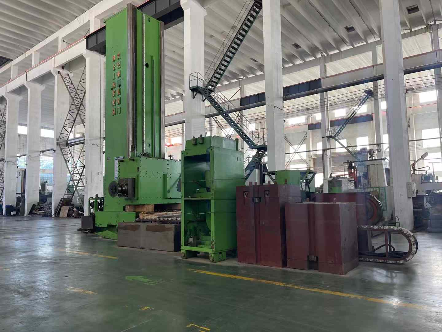
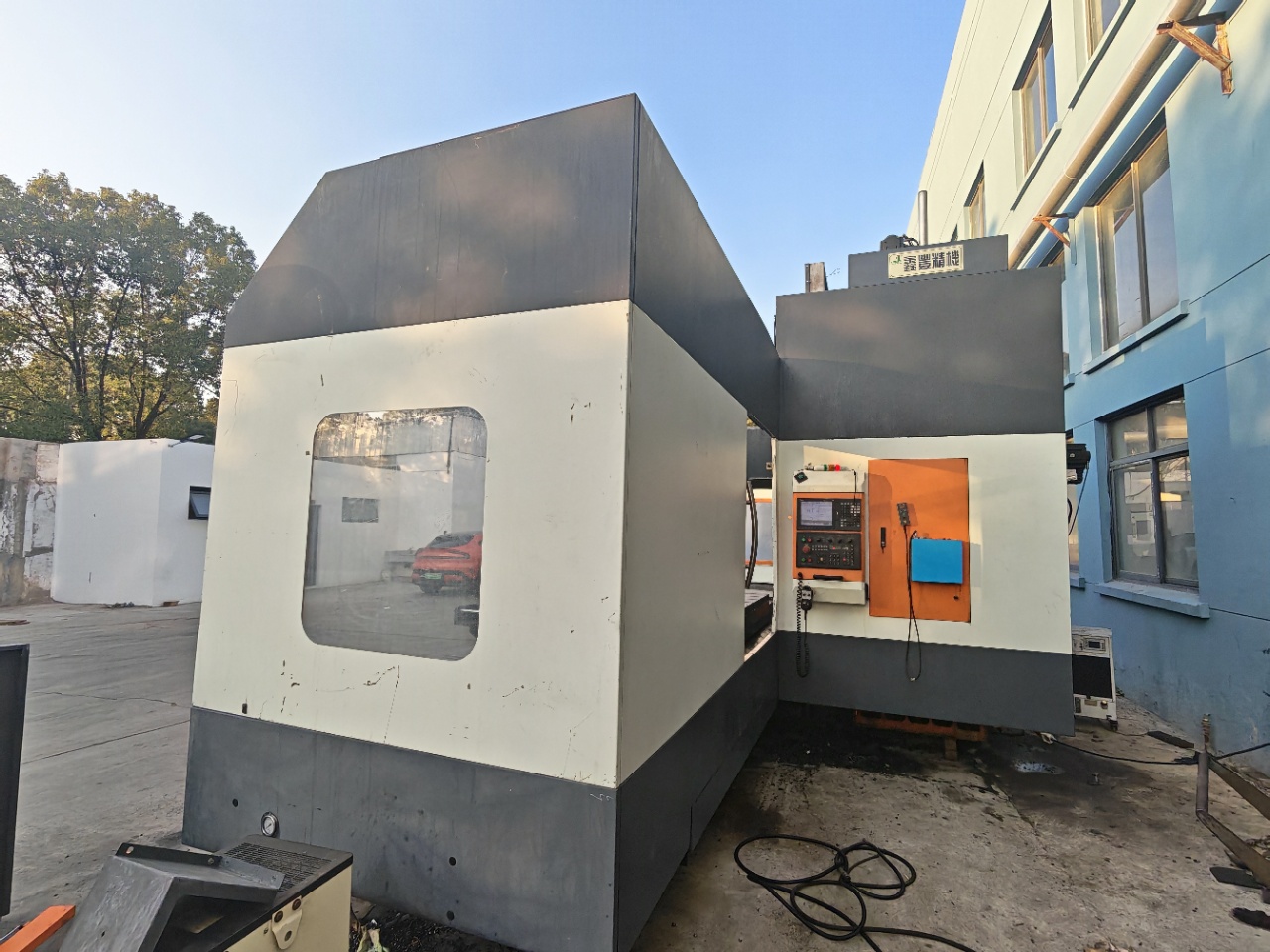
Used FEMCO BMC-110R1 CNC Boring and Milling Machine
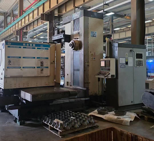
Stock Number: 811824 | Available for Immediate Inspection
The FEMCO BMC-110R1 is a heavy-duty floor-type CNC boring mill engineered for complex, large-scale part processing. Featuring a 4000kg table load capacity, 3-axis box way construction, and a 60-tool automatic tool changer (ATC), this machine is built for shops handling large components, precision molds, and multi-sided machining. This 2012 model is production-ready and available for immediate inspection.
Core Specifications and Shop Floor Performance
Beyond the raw data, the BMC-110R1 is designed to deliver stability and efficiency for demanding production environments.
| Specification | Details |
|---|---|
| Model | FEMCO BMC-110R1 |
| CNC System | Fanuc 21i-MB |
| Table Load Capacity | 4000 kg |
| X-Axis Travel | 1400 mm |
| Y-Axis Travel | 1390 mm |
| Z-Axis Travel | 1050 mm |
| W-Axis Travel | 500 mm |
| Tool Changer | 60-Tool ATC |
| Rotary Table Accuracy | 0.001° |
| Guideways | 3-Axis Box Ways |
| Additional | 4th Axis with Linear Scale |
Rigidity and Vibration Damping
The 3-axis box way construction provides the foundation for this machine's performance. Unlike linear guide systems, which prioritize rapid traverse speeds, box ways offer a larger contact surface area. This is critical for heavy-duty milling and boring, where superior vibration damping is required to achieve tight tolerances and high-quality surface finishes on dense workpieces.
The Significance of the W-Axis
The 500mm W-axis (quill travel) allows the spindle to extend significantly from the machine head. In practical production, this is vital for deep-hole boring or reaching into deep cavities of complex housings. This capability eliminates the need to reposition heavy workpieces, thereby maintaining positional accuracy and reducing setup time.
Capacity for Complex Tooling
The 60-tool ATC is a significant advantage for a machine in this class. It supports a wide range of cutters, drills, and boring bars, enabling complex, multi-step machining sequences without manual intervention. This is particularly beneficial for "lights-out" production or high-mix, low-volume shops where frequent tool changes are standard.
Applications and Workpiece Compatibility
The BMC-110R1 offers exceptional versatility. Its combination of a 4000kg table capacity and 0.001° indexing accuracy bridges the gap between a traditional heavy-duty boring mill and a high-precision machining center.
Ideal Applications:
- Large Industrial Castings: Engine blocks, pump housings, and gearbox casings requiring heavy material removal.
- Precision Molds and Dies: The 0.001° rotary table enables the precise angular machining required for complex mold parting lines and cooling channels.
- Aerospace Components: Structural frames and large housings demanding high positional accuracy across multiple faces.
- Energy Sector Parts: Flanges, valve bodies, and turbine components requiring both structural integrity and geometric precision.
The 4th axis with a linear scale ensures that table indexing is verified by the scale rather than relying solely on the motor encoder. This provides the reliability needed for high-tolerance work where angular deviation could lead to scrapped parts.
Why the BMC-110R1 Fits Your Production Needs
When selecting a used boring mill, the BMC-110R1 offers distinct advantages for production managers:
- Fanuc 21i-MB Control: Widely recognized for reliability and ease of integration. Operators familiar with Fanuc will face a minimal learning curve, reducing downtime during commissioning.
- Optimized Work Envelope (X:1400, Y:1390, Z:1050): This machine is perfectly sized for medium-to-large parts. It provides an ideal balance of footprint and capacity for components that exceed standard VMC envelopes but do not require massive floor-type boring mills.
- Operational Versatility: By combining boring capabilities (W-axis) with milling capabilities (ATC and rotary table), this machine acts as a "one-stop" station, reducing the need to move heavy parts between machines—a process that often introduces error and increases handling time.
Is This Machine Right for Your Facility?
The FEMCO BMC-110R1 is an ideal solution if:
- You are currently outsourcing large, complex parts due to capacity constraints.
- Your current VMCs struggle with vibration during heavy boring or face milling on cast iron or steel.
- You require multi-sided machining that demands precise angular indexing.
- You need a machine capable of both aggressive roughing (thanks to box ways) and high-precision finishing (thanks to the 0.001° indexing and Fanuc control).
While this machine may be over-specified for small, light parts, it is a robust solution for shops dealing with heavy, complex, or high-value components looking to increase throughput.
Frequently Asked Questions
- Q: Is the 4th axis on this BMC-110R1 suitable for continuous milling or just positioning?
- A: The 0.001° rotary table is designed for high-precision positioning. While robust, its primary advantage is the ability to index to precise angles for multi-sided machining, making it well-suited for applications requiring high angular accuracy.
- Q: What is the main advantage of the box ways on this machine compared to linear guides?
- A: Box ways provide superior vibration damping and rigidity. This is critical for heavy-duty boring and milling operations where you need to maintain surface finish and dimensional accuracy while taking deep cuts in tough materials.
- Q: Can the 60-tool ATC handle heavy boring bars?
- A: Yes, the ATC is designed to manage a variety of tooling, including standard boring bars. Always ensure your tooling setup adheres to the weight and length limits specified in the original manufacturer’s manual for the tool changer mechanism.
- Q: Is this machine suitable for mold making?
- A: Yes. The combination of the rigid box-way structure (for mold base machining) and the 0.001° rotary table (for precision angular machining of mold cavities) makes it a versatile choice for mold shops handling medium-to-large molds.
- Q: What does the W-axis travel specifically do for my production?
- A: The W-axis allows the spindle to extend outward. This is essential for boring deep holes or reaching into complex part geometries without moving the workpiece, which saves time and maintains alignment accuracy.
More Articles
-
How to Choose a Boring Machine for Excavator and Loader RepairsChoosing a boring machine for excavator repair starts with the damaged part. Pin bores, bucket linkages and boom connections place different demands on alignment, access and machine setup. For loader work, the same principle applies to articulation points and pivot bores. Identify the repair location first, then match the machine to the bore diameter, available working space and required installation method. Match the machine to the damaged component Equipment Part Typical Repair Requirement Excavator pin bores Restore worn or oval bores while keeping the bore aligned through the connected lug structure. Bucket linkage Repair multiple linkage bores with controlled positioning around compact, obstructed assemblies. Boom and arm connections Handle larger pivot bores and maintain alignment between separated mounting ears. Loader articulation points Recondition central hinge and pin bores where access, clearance and machine positioning affect setup. Loader pivot bores Remove wear and prepare the bore for a replacement or repaired pin with consistent geometry. Start with the bore problem Excavator pin bores commonly develop ovality, uneven wear and clearance around the pin. A suitable boring machine for excavator repair should allow the operator to establish a stable reference, align the cutting bar with the original bore centerline and remove only the material needed for the repair. If several connected bores are involved, the machine must support a setup that preserves their relationship. For bucket linkage and boom or arm connections, access can determine machine fit. Check whether the boring bar can pass through the assembly, whether the mounting points provide enough room for supports, and whether nearby hydraulic lines or structural members restrict positioning. A compact setup may be essential for on-site repair, while a larger and more rigid arrangement may suit a major pivot bore. Requirements for a boring machine for loader repair Loader articulation points and pivot bores require careful attention to alignment because the repaired bore affects hinge movement and pin loading. Before selecting equipment, record the bore diameter, bore length, distance between bores, access direction and available clearance around the loader frame. These details help determine the cutting-bar arrangement, support placement and whether the repair can be completed without removing the full assembly. Site conditions also influence the choice. Confirm the power supply, lifting and handling options, working height, weather exposure and space for measurement and machining. Buyers should verify the machine’s usable diameter range, boring-bar length, mounting method, alignment procedure and suitability for the specific excavator or loader component. Information to send before requesting a recommendation Equipment type and the exact repair location Measured bore diameter, length and wear condition Pin dimensions and whether bushes will be installed Photos showing access, obstructions and surrounding structure On-site or workshop repair conditions, including available power This information allows a supplier to assess machine fit against the actual repair rather than the equipment model alone. FAQ: excavator and loader bore repairs Can one machine repair excavator pin bores and loader articulation points? It may, if its diameter range, bar length, support arrangement and mounting options suit both components. Verify each repair dimension and access condition before selecting a general-purpose setup. What should be measured on a worn excavator bore? Measure the existing bore diameter at several positions, identify ovality and taper, record bore length, and check the mating pin and surrounding lug alignment. These measurements define the machining allowance and setup requirements. What information is needed for a boring machine for loader repair? Provide the loader model, articulation or pivot location, bore and pin dimensions, photos of the working area, access direction, clearance and site power conditions.
-
Boring Machine for Mining Equipment: What Buyers Should ConsiderMining equipment repair rarely takes place in a clean workshop. A boring machine for mining equipment must work around abrasive dust, moisture, limited access, heavy components and urgent production schedules. For procurement teams, the right choice depends on the actual repair environment and the equipment being serviced, not only on the machine's advertised capacity. Start with the Mining Repair Environment First assess where mining equipment boring repair will occur. An underground site may require a compact, portable machine that can be positioned around a loader, excavator or haul truck without removing the complete structure. An open-pit maintenance area may allow more room, but still exposes equipment to dust, vibration, mud and temperature changes. Ask suppliers how the machine is protected during transport and operation. Check the accessibility of controls, the method used to secure the machine to the workpiece, and how easily chips and contamination can be cleared from critical moving parts. A field repair system should also support practical setup, alignment and inspection procedures when workshop equipment is unavailable. Match the Machine to Equipment Constraints Mining repair requirement What to verify Why it matters Large pins and pivot bores Applicable bore diameter range, bar length and tooling options Prevents the machine from being undersized for major joints Restricted access Portable configuration, mounting method and clearance requirements Determines whether repair can be completed in position Hard or damaged material Drive power, feed control and compatible cutting tools Supports stable cutting under demanding repair conditions Multiple equipment types Adjustability, modular components and available accessories Improves utilization across different machines and bore sizes Do not evaluate bore diameter alone. Confirm the complete working envelope: minimum and maximum bore size, usable boring-bar length, mounting span, alignment method and access around the damaged joint. The machine must also suit the metallurgy and damage condition commonly found in the fleet. Evaluate Power, Durability and Maintenance Power should be considered together with control. A suitable drive system needs enough torque for the planned cutting tools and materials while maintaining controlled rotation and feed. Ask for application guidance based on the actual equipment, bore dimensions and repair material rather than relying on a general power figure. For mine-site use, inspect wear-prone parts, seals, bearings, cables, gear components and mounting hardware. Request a clear maintenance schedule and identify which parts can be inspected or replaced by site technicians. Spare-part availability is a procurement issue, not an after-sales detail: delays involving a drive component, cutter or fastening element can extend equipment downtime. Check Engineering Support Before Purchase Supplier support should cover configuration, setup, alignment, tooling selection and troubleshooting. Before issuing a purchase order, request a documented list of included components, optional accessories, recommended consumables and spare parts. Verify training or commissioning arrangements where the repair team has limited experience with portable line boring. Also confirm how the supplier handles unusual bore sizes, difficult access and repairs requiring additional fixturing. A durable machine is valuable only when the site team can install, operate, maintain and restore it with dependable technical support. FAQ: Mining-Site Durability and Maintenance Can a portable boring machine be used in underground mining repairs? It can be suitable when its dimensions, mounting method, power source and access requirements match the underground work area. Confirm transport limitations and the available space around the damaged bore before selection. What maintenance information should buyers request? Request inspection intervals, lubrication requirements, wear-part identification, troubleshooting procedures and a recommended spare-parts list. The documentation should explain which maintenance tasks can be completed at the mine site. Why is engineering support important for mining equipment boring repair? Mining repairs often involve irregular access, large structures and varying bore conditions. Technical support helps determine the correct machine configuration, tooling and alignment method before equipment downtime becomes longer.
-
How Boring Machines Restore Worn Bores in Heavy MachineryWhen a pin, bushing or shaft moves excessively in a heavy-machine bore, replacing the loose component alone may not solve the problem. The bore may be oval, tapered, scored or out of position. A boring machine for heavy machinery can restore the bore’s geometry by machining it to a planned size and alignment, often with the work performed on the machine rather than removing the full structure. Diagnose the damage before machining Start by cleaning the joint and recording the machine model, component location, bore dimensions and symptoms. Measure the bore at multiple positions and orientations to identify wear, ovality and taper. Inspect for cracks, fretting, corrosion, damaged welds and movement around the bore. Check the pin or shaft and mating bores as well: a worn pin, failed lubrication or misaligned joints can cause repeat damage. Common cause Typical clue Repair consideration Insufficient lubrication or contamination Scoring, heat marks or abrasive wear Correct the lubrication or sealing issue as part of the repair plan. Loose fit or worn pin Knocking, fretting or uneven contact Assess both bore and pin; machining only the bore may leave excessive clearance. Misalignment or structural movement Uneven wear across connected bores Establish the required common axis before line boring. Corrosion, impact or fatigue Pitting, deformation or visible cracking Determine whether the material can be safely repaired before cutting. Alignment determines the repair For connected joints, line boring worn bores aims to restore their relationship to a common axis. A bore can be round yet still be incorrectly positioned relative to the next bore. The repair plan therefore needs reference points, the required axis, finished diameter and fit requirements, plus any limits on material removal. If damage is severe, cracks are present or the original geometry cannot be established, confirm the repair method with the equipment owner or a qualified engineering authority before machining. Machine, then verify the finished joint After fixing the setup and boring bar, the technician aligns the tooling to the agreed reference, removes material in controlled passes and checks progress against the target. Depending on the repair design, the finished bore may receive a sleeve or bushing; the installation and final size must match the specified fit. Protect nearby surfaces and components from chips, and follow site isolation and machine-support procedures throughout the work. Final inspection should verify diameter at several points, roundness, alignment across the connected bores and surface condition. Check the installed pin or bushing fit against the applicable drawing or repair specification. Record measurements and any deviations, then address the cause of wear before returning the machine to service. Information to provide when assessing a repair Share bore locations and access constraints, measured dimensions, photos of damage, machine and component details, pin or bushing condition, and the required fit or drawing. Include operating symptoms and known lubrication, impact or alignment issues. These job details help determine whether on-site boring, a sleeve-based repair or further engineering assessment is appropriate. FAQ Can a worn bore be repaired without removing the component? Often, portable line boring can be set up on installed machinery, but access, setup stability, damage severity and alignment references determine feasibility. How do you confirm the repair is complete? Measure the finished diameter and geometry, verify the axis where bores are connected, and check the pin or bushing fit against the repair specification. Will boring alone prevent the bore from wearing again? No. Boring restores geometry; recurring wear may continue unless the underlying cause, such as poor lubrication, contamination, a damaged pin or misalignment, is corrected.
-
How to Select a Boring Machine for Heavy Equipment Repair and MaintenanceWhen an excavator, loader or crane develops play at a pin joint, the repair decision starts with the damaged bore and where the work must be done. Selecting a boring machine for heavy equipment means matching the machine’s working range and setup to the equipment, bore geometry and repair environment, not choosing by machine size alone. Start with the equipment and bore Repeated loading, vibration and movement can wear pivot bores out of round or enlarge them. Damage may affect a boom, arm, bucket, blade, steering joint, stabilizer or other connected structure. Bulldozers and mining machinery can present similar issues, often with limited access and substantial components that are difficult to transport. Before comparing machines, identify the bore location, nominal and measured diameter, bore length, spacing between bores, and whether the holes must share a common axis. Also note obstructions, available mounting points and the clearance needed for the bar, supports and drive. These details define the required working range and setup options for heavy equipment line boring. Match the machine to the repair setting Repair scenario Selection priority Excavator boom, arm or bucket joint Bar reach, mounting access and alignment across separated bores Loader linkage or articulation joint Setup flexibility around the frame and room for the drive and supports Bulldozer blade or ripper attachment Access around large structures and practical positioning at the machine Crane pivot or stabilizer connection Clearance, stable mounting and the required bore length Mining machinery with limited shutdown access Transportability, on-site setup requirements and available power For on-site boring repair, consider whether the machine and accessories can be moved to the equipment, whether the work area allows safe setup, and what power and lifting support are available. If the component can be removed and handled in a workshop, compare that option with field machining based on transport, downtime and access constraints. Check configuration before purchase Compare the machine’s stated bore-diameter range, bar length, support arrangement, drive configuration and mounting method with the actual jobs you expect to handle. Confirm whether the configuration can accommodate the bore spacing and access limits, and whether the required accessories are included or optional. A nominal diameter range alone does not confirm that a machine can reach a particular joint or maintain the required alignment. Share equipment type, bore dimensions, distance between bores, photos of the joint and site constraints when requesting a configuration. Ask the supplier to verify working range, mounting approach, power requirements and any accessories needed for the stated job. Keep this selection decision separate from the repair procedure: machining sequence and bore restoration methods depend on the damage and repair specification. Questions buyers often ask Can one boring machine cover excavators, loaders and cranes? Possibly, if its working range, bar length, mounting options and accessories suit the different joints. Verify each target bore and setup rather than assuming one configuration fits every machine. What information is needed for an on-site recommendation? Provide bore diameter and length, spacing between bores, joint photos, access restrictions, available power and whether the equipment can be moved or dismantled. Does a larger machine always suit heavier equipment? No. The useful choice is the configuration that reaches and mounts securely at the bore while meeting the job’s dimensional and alignment requirements. Oversizing alone does not solve access or setup problems.